CNC Hole Position Tolerance for Quote-Ready Parts
Published 2026-10-12 · Tolerances

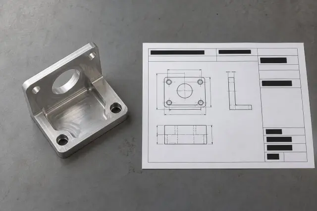
CNC hole position tolerance controls where a hole axis may lie from its basic location relative to datums; diameter alone does not. For 4X Ø6.6 mm clearance holes on a 40.00 × 25.00 mm basic pattern, position ⌀0.20 mm | A | B | C at MMC controls the pattern’s assembly location.
At quote stage, the key question is not whether your STEP file shows four holes. It is whether the drawing defines the surfaces that locate those holes after machining, inspection, and re-clamping. That choice changes the fixture plan, inspection method, and assembly risk.
What does CNC hole position tolerance control?
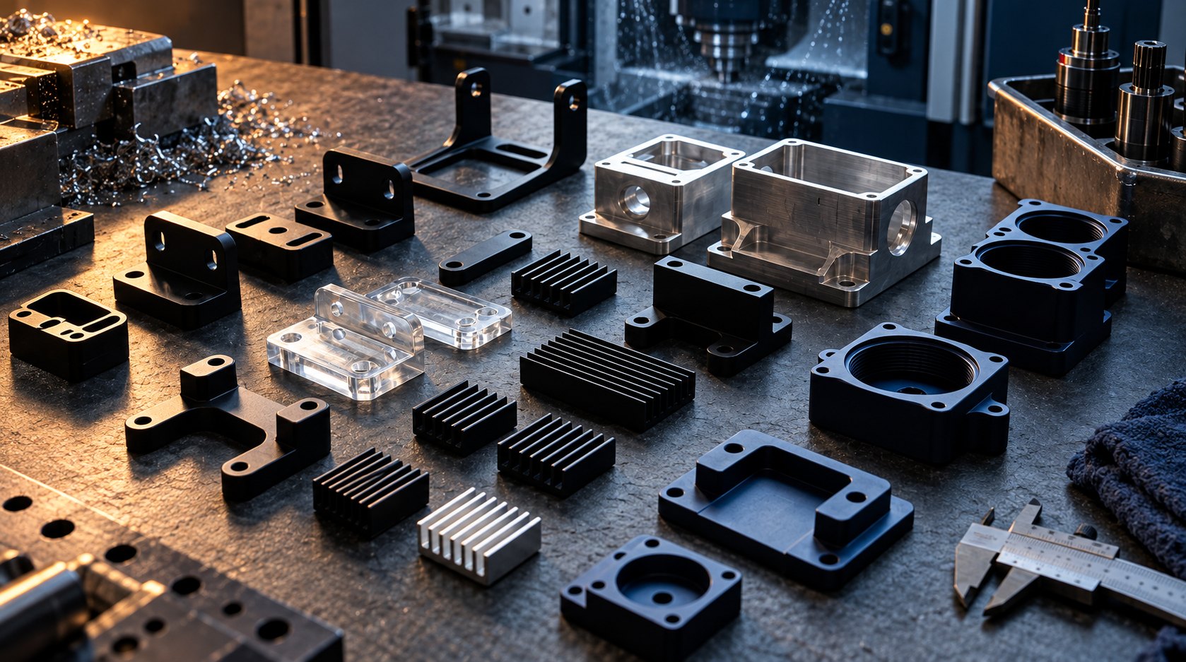
CNC hole position tolerance controls the hole’s axis within a cylindrical zone located from the referenced datum reference frame. A diameter callout controls size. It does not establish where the hole center sits on the part.
That is why a separate Ø10.00 ±0.02 mm diameter callout does not control location. The bore may measure between 9.98 mm and 10.02 mm while its axis is still displaced from the mating feature. You need basic dimensions and a position control tied to functional datums.
ASME Y14.5-2018 Section 7 covers location tolerances, including position. At MMC, the hole can receive bonus tolerance as its actual size departs from MMC. For a clearance hole, that extra positional freedom may be useful. It should not replace a datum scheme.
For the 4X Ø6.6 mm example, the 40.00 × 25.00 mm dimensions define the basic pattern. The feature control frame defines the allowable pattern location relative to A, B, and C. The diameter and the pattern answer different inspection questions.
Why can the hole diameter pass while assembly fails?
A bolt pattern can pass diameter inspection but not align after a re-clamp because datum B was undefined. Without B, the pattern can shift relative to the part even when every hole has the correct diameter.
Capvidia explains that a multi-hole position pattern without a datum reference frame can move relative to the part. OEMach identifies datum mismatch, re-clamping, thermal drift, burrs, tool compensation, and inspection logic as common contributors.
The practical failure is easy to miss. A shop drills four holes, measures each diameter, and reports a pass. The mating plate is then installed after the bracket has been removed and re-clamped. The undefined secondary datum allows the pattern to rotate or translate enough to block the bolts.
If the broader drawing review also contains unrelated process risks, the article CNC Machining Design Mistakes Cost You More Than You Think is the next useful check. Keep this review focused on location, datums, and assembly.
How do you turn a STEP upload into a quote-ready datum scheme?
A STEP model reveals the hole pattern and surrounding geometry, but it cannot reliably infer which faces are functional datums. You must provide the datum intent, hole function, and inspection reference before the quote can reflect assembly risk.
- Identify the face that seats against the mating assembly and label it primary datum A. Failure mode: the shop establishes the coordinate system from a convenient face instead of the seating face.
- Choose the secondary datum B from the feature that prevents translation or rotation in service. Failure mode: B is left undefined, so a re-clamp changes the bolt pattern’s relationship to the bracket.
- Choose tertiary datum C and mark the basic 40.00 × 25.00 mm pattern. Failure mode: center-to-center dimensions are inspected without checking the pattern against the part datums.
- Add the position control, MMC modifier, and any required projected or composite control. Failure mode: a diameter callout is mistaken for a location requirement.
- Tell the quote team the material, quantity, critical surfaces, and inspection method. Failure mode: thermal drift, burrs, or a datum mismatch appears only after first-article inspection.
On an anonymized 6061-T6 aluminum bracket, one internal check recorded positional deviations of 0.06, 0.08, 0.12, and 0.16 mm across a four-hole pattern from the defined A|B|C frame. The holes passed the specified position zone. That result depended on inspecting the bracket from the same datum scheme used for machining.
CNC Instant Quote can read the geometry for milling or turning in aluminum, copper, brass, steel, and plastics. The model supports instant pricing, but functional datums still come from your drawing or engineering notes. If your part could be made on different equipment, compare CNC Router vs Mill: Choose from Your CAD before finalizing the process assumption.
Quote structure also changes with inspection and setup needs. A datum-controlled four-hole bracket may require a stable fixture and CMM verification, while a simple clearance plate may need only basic dimensional checks. For broader cost context, see CNC Machining Tariffs 2026: Why Your Quote Costs More.
Which hole types need tighter position control?
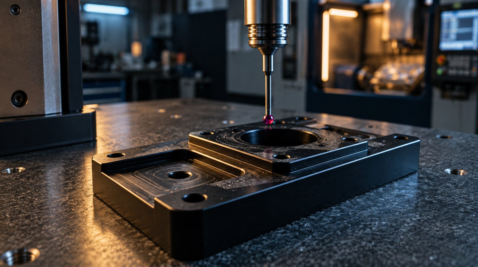
Hole function should determine position control. Clearance holes usually need assembly space, while dowel holes, bearing bores, and locating features need a defined relationship to the mating parts.
| Hole type | Primary control | Use when | Quote and inspection effect |
|---|---|---|---|
| Clearance holes | Moderate position control tied to mating faces | A bolt shank can float inside the hole | Prioritize fixture repeatability and pattern alignment over an unnecessarily tight diameter. |
| Dowel holes | Tight diameter and position from functional datums | The pin locates the assembly | Expect controlled reaming or finishing and datum-based inspection. |
| Threaded mounting holes | Position sufficient for screw engagement and access | Fasteners clamp parts without locating them | Check tool access, thread depth, and bolt pattern alignment; do not assume thread diameter controls center location. |
| Bearing bores | Diameter, axis relationship, and position to mating features | A bearing seat controls rotation or shaft alignment | Plan stable setups and targeted inspection for the bore and its reference surfaces. |
NAITE TECH’s tolerance guidance makes the same functional distinction: dowel holes, bearing seats, sealing surfaces, and mating interfaces deserve focused control, while non-functional clearance features often do not. This is how you control cost without weakening the assembly.
What should your quote and inspection plan state?
Your quote package should state the functional datum frame, hole class, material, quantity, and inspection requirement. A STEP file alone shows geometry; it does not state whether a hole locates, clamps, clears, seals, or supports a bearing.
- Identify A, B, and C on the 2D drawing or engineering note.
- Separate diameter tolerance from hole position tolerance.
- Mark MMC where bonus tolerance is intended.
- Flag dowel holes, bearing bores, and locating patterns as functional features.
- State whether inspection uses a CMM, functional fixture, pin gauge, or another method.
- Call out re-clamping risk when holes span multiple faces or setups.
For supplier-quality questions, the ISO 9001:2026 Supplier Questions for Machined Parts guide helps you ask how the inspection coordinate system, records, and corrective actions are controlled.
FAQ: CNC hole position tolerance
Does hole diameter tolerance control hole location?
No. Diameter controls the size of the opening. Position tolerance controls the hole axis relative to the referenced datums.
What does MMC add to a position tolerance?
MMC allows bonus position tolerance as the actual feature departs from its maximum material size. The datum reference frame still controls the location.
Can a STEP file define the GD&T hole pattern?
Not reliably by itself. STEP geometry shows nominal faces and holes, but your drawing or notes must identify functional datums and inspection intent.
What causes a bolt pattern to fail after re-clamping?
Undefined or mismatched datums, fixture variation, thermal drift, burrs, and inspection from a different coordinate system can all move the pattern.
Make your CNC hole position tolerance quote-ready
Define the datum frame before you define the price. For the 4X Ø6.6 mm pattern, show A, B, and C, retain the 40.00 × 25.00 mm basic dimensions, and state position ⌀0.20 mm at MMC. Then identify which holes locate the assembly and which only provide clearance.
Upload the STEP model with the drawing, material, quantity, and inspection notes. CNC Instant Quote will use the CAD geometry for an engineering-driven quote, while your datum scheme determines whether the finished part will assemble. Review our CNC machining service for the available milling and turning capabilities, then send the files →
Related guides
Price your part in seconds
Upload a STEP or IGES file — real geometry, real pricing, no waiting.